
Operational Failures of Wet Electrostatic Precipitators (WESP) in Power Plants: Analysis and Troubleshooting
Introduction: The Rising Environmental Stakes in Coal-Fired Power Generation
The rapid expansion of thermal power capacity combined with increasingly stringent environmental mandates—such as China’s strict GB13223-2011 emission standards—has placed immense pressure on coal-fired power plants. Traditional air pollution control devices face severe technical bottlenecks. Standard Wet Flue Gas Desulfurization (WFGD) systems, while effective at removing bulk sulfur dioxide SO2, struggle to capture fine particulate matter PM2.5, mercury, and sulfur trioxide SO3 aerosols.
This technological gap frequently leads to downstream environmental hazards, notably “gypsum rain,” acid mist, and the notorious “blue or yellow smoke” plumes from stacks. To achieve true ultra-low emissions and mitigate these persistent pollutants, the industry requires a highly efficient, large-scale, terminal multi-pollutant control technology. The Wet Electrostatic Precipitator (WESP) has emerged as the definitive solution to these challenges.
1. The Evolution and Power Plant Integration of WESP
Originally introduced in 1977 to control sulfuric acid mist, WESP technology matured over decades within the metallurgical and chemical processing industries. Its transition to the power generation sector was catalyzed by the widespread adoption of WFGD systems.
Because WFGD processes leave the flue gas thoroughly saturated, they create an ideal downstream environment for WESP integration. Positioned as the final polishing step before the stack, the WESP utilizes this saturated environment to maximize particle collection efficiency without the risk of re-entrainment.
2. Fundamental Working Principles of WESP
A standard WESP system comprises the precipitator casing (body), a closed-loop water circulation system, high-voltage rectification equipment, and low-voltage control systems.
Unlike Dry Electrostatic Precipitators (ESP) that rely on mechanical rapping to dislodge ash, a WESP utilizes a continuous water film flush to clear the collecting electrodes, routing the captured pollutants directly into a hopper.
The Four Core Physical Processes of WESP
- Gas Ionization: High-voltage electrodes ionize the passing flue gas, generating a dense field of corona discharges.
- Agglomeration and Charging: Suspended dust particles and aerosol droplets collide with these ions, acquiring a negative charge.
- Migration: Charged particles migrate toward the positively charged collecting electrodes under the influence of the electrostatic field force.
- Water Film Remobilization: A continuous, gravity-driven water film on the collection plates washes the captured material away, maintaining a clean surface and high electrical efficiency.
3. Structural Design and the Closed-Loop System
The engineering design of a WESP offers distinct operational advantages over dry alternatives. Replacing mechanical rapping mechanisms with an integrated spray system completely eliminates secondary dust re-entrainment. Furthermore, the high moisture environment dramatically lowers dust specific resistance, allowing the system to operate at significantly higher voltages without back-corona issues.
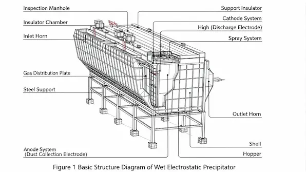
The main structural components include the casing, internal collector plates and discharge electrodes, high-voltage inlet lines, inlet/outlet gas distribution horns, ash hoppers, an insulator thermal hot-air sweeping system, and the dedicated water supply/spray infrastructure. This creates a highly efficient closed-loop system:
Water Film Cleans Plates —> Wastewater Directed to Treatment —> Recycled/Filtered Water Return
4. Key Performance Advantages of WESP
- Exceptional Operational Stability: Performance remains uninfluenced by variations in coal type, ash chemistry, or dust specific resistance. Because the unit contains no moving parts, mechanical wear is practically non-existent.
- Guaranteed Ultra-Low Emissions: WESP systems consistently drive outlet particulate matters down to under 10mg/Nm3, meeting and exceeding global clean air benchmarks.
- Comprehensive Environmental Benefits: The system achieves a ≥90% removal rate for PM2.5 and SO3 mist, reducing stack opacity to near-zero levels. It effectively eliminates “gypsum rain” and blue smoke while mitigating downstream flue and stack corrosion, thereby lowering long-term plant maintenance costs.
5. Technical Limitations and Operational Constraints
Despite its strengths, a WESP requires specific process boundaries to prevent structural failure:
- Flue Gas Temperature: The incoming gas must be cooled below its saturation temperature. Robust anti-condensation measures are mandatory for internal components.
- Upstream Pollutant Loads: WESPs are not designed for bulk ash removal; they cannot directly handle raw, high-grain dust or extreme SOx concentrations.
- Material and Subsystem Overhead: The system demands dedicated wastewater treatment facilities. Additionally, internal core components (discharge and collecting electrodes) must be fabricated from highly corrosion-resistant materials (such as high-grade stainless steels or conductive plastics) to withstand acid attack.
Strategic Optimization: Placing the WESP directly downstream of the Wet Flue Gas Desulfurization (WFGD) unit perfectly addresses the first three constraints by naturally providing a cooled, pre-scrubbed, and low-dust flue gas feed.
6. Strict Commissioning and Start-Up Protocols
To safeguard the longevity of internal linings and electrical components, operators must strictly adhere to the following start-up sequence:
- Preheating Phase: Activate the insulator compartment electrical heaters and hot-air sweeping system at least 8 hours prior to introducing flue gas. Ensure temperatures stabilize above 60℃ to prevent condensation on insulation surfaces.
- Corrosion Protection: The upstream WFGD system must be fully operational before routing flue gas to the WESP. Never allow dry, high-temperature raw flue gas to bypass or enter the WESP, as this will irreparably damage internal anti-corrosion coatings.
- Interlock Criteria: The WESP must only be energized when boiler load stabilizes, oil guns are completely retracted, flue gas temperature drops below 70℃, and the upstream desulfurization unit is verified online.
- Execution Order: Turn on Low-Voltage Water Supply System —> Energize High-Voltage Power Supply Units
7. Shutdown Protocols and Outage Preservation
When taking a WESP offline, reversing the start-up sequence incorrectly can lead to severe corrosion and component fouling. Use the following procedure:
- De-energization Sequence: Shut Down High-Voltage Power Supplies —> Deactivate Low-Voltage Water Supply/Sprays
- Post-Operation Flushing: After the boiler has completely shut down, the spray system must run continuously for at least 8 hours. This thorough wash is critical to remove lingering acidic deposits and ash residues from the internal collection plates.
- Safety and Preservation: Isolate high-voltage breakers, apply physical lockouts, and hang safety warning tags. For short-term outages, keep the insulator heaters and hot-air sweeping systems fully energized to prevent moisture ingress and condensation.
8. Root-Cause Analysis of Common WESP Failures & Troubleshooting Guide
The following matrix outlines the critical electrical and hydrological failures encountered during plant operations, along with their diagnostic symptoms and field remedies.
| Fault Phenomenon | Diagnostic Symptoms | Root-Cause Analysis | Field Remediation & Action Plan |
|---|---|---|---|
| Internal Transformer Damage |
|
|
|
| Low-Voltage Coil or Core Insulation Failure |
|
|
|
| High-Voltage Cable Current Leakage |
|
|
|
| Excessive/Frequent Field Flashovers |
|
|
|
| Circulating Water pH Fluctuations |
|
|
|
| Drop in Water Flow Rate & Collection Efficiency |
|
|
|
Conclusion and Future Outlook
While international industrial sectors have leveraged Wet Electrostatic Precipitator technology for nearly three decades, its application in domestic coal-fired utilities remains an emerging frontier. Historically relegated to small-to-medium industrial boilers and metallurgy, WESPs are seeing rapid mainstream adoption. As global and national regulatory frameworks move toward a total-control approach for fine particulates, hazardous air pollutants, and condensable aerosols, WESPs represent the most viable pathway forward. For utility managers, mastering both the precise operational discipline and targeted troubleshooting of these units is no longer optional—it is fundamental to ensuring long-term environmental compliance and generating cleaner power.
Did this troubleshooting guide help you optimize your plant’s WESP performance, or are you currently facing a specific electrical fault not covered here?