
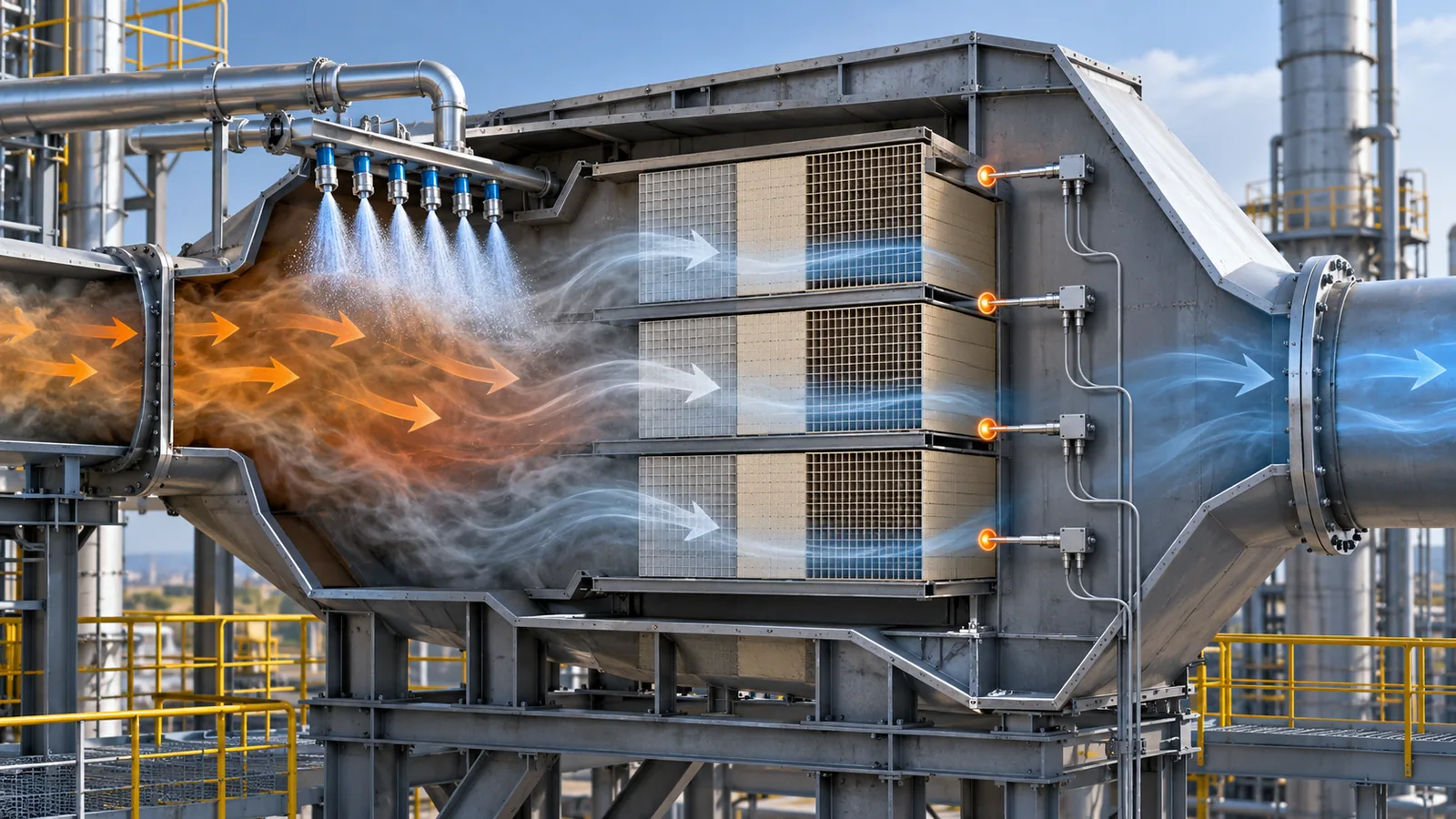
SCR catalyst should not be treated as a fixed-life consumable. A layer may still look intact while its usable activity, pressure drop, ammonia-slip margin or flow distribution has become the real constraint. The lower-risk decision is to manage the catalyst as part of an operating system: fuel and ash, flue-gas temperature, ammonia injection, reactor flow field, sootblowing, catalyst condition and planned outages all interact.
This guide turns that system view into a practical lifecycle workflow. It is written for coal-fired and industrial power applications, but the same evidence-led approach applies whenever an SCR reactor must maintain NOx conversion without allowing ammonia slip or pressure drop to drift beyond plant limits.
The lifecycle question is not “How many years will the catalyst last?”
Service life is conditional. The same catalyst formulation can age at different rates when gas temperature, fly ash, arsenic or alkali exposure, sootblowing intensity, operating hours at load, and inlet distribution differ. A calendar estimate can be useful for budgeting, but it is not a replacement decision by itself.
Instead, manage four linked outcomes:
| Outcome to manage | What a deteriorating trend can indicate | Evidence to review |
|---|---|---|
| NOx conversion | Activity loss, poor NH3/NOx distribution, low temperature or bypassing | Inlet/outlet NOx, load, temperature and reagent trend |
| Ammonia slip | Activity margin loss, uneven injection or mixing, excess reagent | Slip trend, AIG settings, load and gas distribution data |
| Pressure drop | Ash plugging, masking, channel blockage or accumulated deposits | Layer-by-layer ΔP, visual inspection and ash condition |
| Mechanical condition | Erosion, broken elements, sealing failure or support damage | Outage photos, dimensional checks and module inspection |
EPA guidance similarly describes catalyst activity as dependent on catalyst composition and structure, diffusion and mass-transfer effects, gas temperature and gas composition. As activity declines, plants may compensate with more ammonia, which can increase ammonia slip. US EPA SCR Cost Manual
1. Establish a baseline before there is a problem
A useful catalyst management plan begins with a reference condition taken after commissioning, after a verified catalyst change, or after a controlled outage inspection. Record reactor inlet temperature, gas flow, oxygen, NOx distribution, reagent demand, ammonia-slip measurement method, pressure drop by layer, AIG settings and sootblowing regime.
The baseline does not need to be perfect. It needs to be repeatable. Use the same instrument locations, load bands and calculation basis whenever possible. This lets the team see a trend rather than compare unrelated snapshots.
2. Treat inlet distribution and ammonia injection as catalyst-protection work
An uneven inlet flow field or uneven NH3/NOx ratio can make one zone work harder while another zone consumes excessive reagent. The result can resemble catalyst deactivation even when the root cause is mixing or distribution.
Before ordering new catalyst, review:
- Reactor inlet velocity and temperature distribution.
- NOx distribution at the catalyst inlet.
- AIG nozzle condition, pressure balance and zone settings.
- Ash accumulation, turning vanes, duct geometry and flow-obstruction changes.
- Whether the poor performance is local, layer-specific or plant-wide.
CFD modelling and field measurements can be useful when data indicate a distribution issue, but they should validate a defined engineering question rather than become a generic add-on. A corrective action may involve AIG tuning, flow-guiding hardware, cleaning or a revised sootblowing pattern—not automatically a catalyst replacement.
3. Use sootblowing to control deposits without creating erosion
Sootblowing has two failure modes. Too little cleaning can allow deposits and pressure drop to rise. Too much, or poorly directed cleaning, can accelerate erosion and mechanical damage. The correct schedule is condition-based.
| Operating signal | Possible interpretation | First action to consider |
|---|---|---|
| Rising layer ΔP with stable load | Deposit accumulation, plugging or masking | Inspect ash pattern; verify cleaning coverage and frequency |
| Localized wear or broken edges | Excessive cleaning energy, misalignment or high-velocity ash | Check lance alignment, flow field and exposed leading edges |
| Higher ammonia use with stable ΔP | Activity loss or distribution/mixing problem | Review activity data and NH3/NOx distribution before changing layers |
| ΔP and NOx both unstable | Multiple system effects may be present | Correlate load, temperature, ash, cleaning and instrument data |
Use pressure-drop, NOx, load and inspection findings together. A schedule based only on elapsed time can under-clean some conditions and over-clean others.
4. Build outage diagnostics into the replacement plan
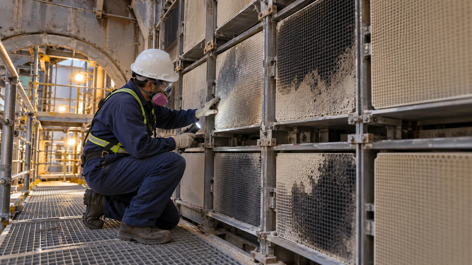
Outages are the best time to turn operating suspicion into evidence. A robust inspection typically combines visual condition mapping with representative catalyst samples and layer-specific data. The exact tests depend on the plant and supplier, but the decision package should distinguish activity loss from plugging, poisoning, erosion and structural failure.
What to document during an outage
- Photograph each layer and map deposits, erosion, broken modules and seal condition.
- Record layer-by-layer pressure-drop history and compare it with visual findings.
- Take samples using a documented location plan; avoid relying on one convenient module.
- Test activity using an agreed method and basis; report the method with the result.
- Review pore/channel blockage, ash chemistry and potential poisons where relevant.
- Reconcile the findings with ammonia demand, slip and NOx trends.
Do not treat an activity number as the whole diagnosis. An apparent activity shortfall may coexist with a distribution problem, and a structurally damaged module may not be a regeneration candidate even when some activity remains.

5. Decide among continued operation, cleaning/regeneration, layer addition and replacement
The decision should compare technical feasibility, emissions risk, outage timing and total operating cost. It should also be layer-specific where the reactor design allows it.
| Decision path | Suitable when | Evidence needed before commitment | Caution |
|---|---|---|---|
| Continue with controls | Performance margin remains and root cause is operational | Stable compliance trend; verified distribution or cleaning corrective action | Do not defer action if margin is shrinking quickly |
| Clean or regenerate | Deposits or recoverable poisoning dominate; substrate is mechanically sound | Sample qualification, activity test, blockage assessment and regeneration proposal | Qualification must be based on representative samples |
| Add a layer | Reactor has spare capacity and total activity needs restoring | Catalyst-management plan, reactor capacity and slip margin review | Confirm flow, structure and system constraints |
| Replace a layer or modules | Activity, pressure drop or mechanical condition is no longer acceptable | Layer-specific diagnosis, inspection and lifecycle-cost comparison | Avoid replacing healthy layers solely on a generic age rule |
EPA’s catalyst-management discussion describes adding catalyst to available reactor layers and using analysis data to identify older layers for replacement. It also notes that regeneration should be prequalified on a catalyst sample. US EPA SCR Cost Manual
6. Calculate the cost of waiting, not only the price of new catalyst
Procurement should compare more than module price. A lifecycle decision can affect ammonia consumption, air-preheater fouling or corrosion exposure, outage scope, cleaning effort, generation or production availability, spent-catalyst handling and compliance risk.
| Cost question | Data input | Decision use |
|---|---|---|
| Reagent penalty | NH3 consumption per load band and conversion target | Shows the cost of compensating for activity loss |
| Pressure-drop penalty | Fan power, operating range and blockage trend | Quantifies the cost of restricted gas flow |
| Outage opportunity | Planned outage duration and critical-path work | Helps avoid forced or poorly timed work |
| Compliance margin | NOx and ammonia-slip trend against the plant’s applicable limits | Defines urgency and risk |
| Disposal / regeneration | Sample result, logistics and permitted pathway | Compares recoverable value with replacement cost |
The decision should be documented with assumptions. That makes it possible to review the outcome after the next outage and improve the management plan instead of repeating the same emergency decision.
A 90-day SCR catalyst management cadence
| Cadence | Core task | Output |
|---|---|---|
| Weekly | Review NOx, ammonia demand, slip, ΔP and load trends | Exceptions and operating hypotheses |
| Monthly | Compare distribution, cleaning and layer trends | Corrective-action priority list |
| Quarterly | Review remaining activity margin and planned outage scope | Forecast and budget update |
| Before outage | Lock the sampling, inspection and test plan | Decision-ready evidence package |
| After outage | Update baseline, activity model and next review date | Revised catalyst management plan |
What to send for a catalyst lifecycle review
To receive a technically comparable recommendation, provide the reactor drawing and layer configuration; design and actual gas flow; temperature and oxygen range; fuel/ash chemistry where available; NOx and ammonia-slip trend; reagent consumption; layer ΔP; AIG and sootblowing settings; photos; and previous test reports. This evidence allows a supplier to distinguish a catalyst requirement from a distribution, cleaning or mechanical problem.