
Deep turndown changes the job of a coal-fired unit’s selective catalytic reduction (SCR) system. Lower load can bring the economizer-outlet gas temperature closer to the catalyst’s minimum operating limit while NOx production, flow distribution and ammonia demand change at different rates. The operator may still meet the stack NOx target at one instant yet create excessive ammonia slip or a rising air-preheater differential pressure later.
The practical rule is to control the complete operating envelope, not NOx alone. Before changing the ammonia setpoint, verify catalyst-inlet temperature, measurement lag, NH3/NOx distribution and downstream fouling indicators. A control algorithm cannot recover reaction activity when the reactor is outside the catalyst’s approved temperature range.
China’s 2025–2027 coal-power upgrade plan calls for existing units, depending on configuration, fuel and heat supply, to reach minimum output of 25–40% of rated capacity; a new-generation demonstration target is below 20%. Those are policy targets for China—not universal SCR design limits or a promise that any individual unit can operate safely at that load.
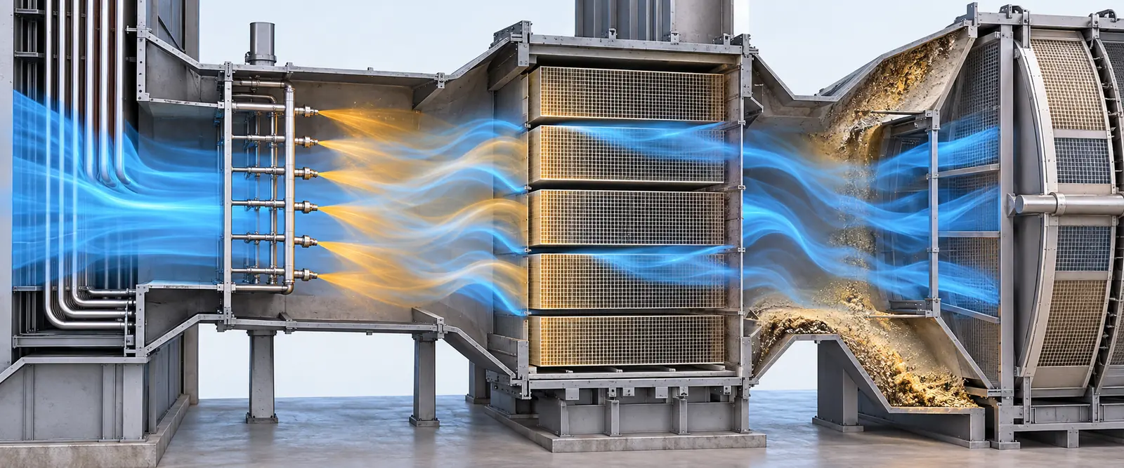
What changes in the SCR system as load falls?
An SCR reactor reduces NOx by reacting it with injected ammonia over a catalyst to form nitrogen and water. For a high-dust coal unit, the reactor normally sits between the economizer and air preheater. Lower load affects the three inputs that matter most: temperature, mixing and residence conditions, and the timing of the NOx measurement used for control.
Traditional coal-unit SCR installations often operate around 300–400°C, but the valid window is catalyst- and site-specific. Use the supplier’s performance guarantee, minimum ammonia-injection temperature and plant operating procedure, not a generic number. DOE/NETL notes that many installations need an SCR inlet above roughly 288–316°C for design-life performance; it also warns that low-temperature operation can create ammonium-bisulfate risks. DOE/NETL flexibility assessment
At reduced temperature, conversion can fall. Increasing ammonia simply to force the outlet NOx number down may raise unreacted NH3. Where SO3 and moisture are present, ammonium bisulfate (ABS) can form and deposit in catalyst pores or downstream air-heater surfaces. The risk depends on fuel sulfur, SO3 formation, gas temperature, local NH3 concentration and the air heater’s metal-temperature profile; SO2 alone is not an adequate predictor. US EPA SCR performance report
Reduced gas flow can also change velocity and NOx profiles across the duct. A fixed ammonia-injection-grid (AIG) balance tuned at full load may overfeed one zone and underfeed another. A single average NOx value can hide that maldistribution.
Low-load SCR troubleshooting: match the symptom to the first check
| Symptom during turndown | Likely contributors—not a diagnosis | First evidence to check | Sensible next step |
|---|---|---|---|
| Outlet NOx rises as load falls | Catalyst inlet too cool; inlet NOx change; delayed feedback; insufficient mixing | Load-banded inlet temperature and inlet/outlet NOx trends with time stamps | Verify temperature permission and instruments before increasing NH3 |
| NOx oscillates after load ramps | Analyzer transport delay, controller tuning, valve deadband or changing combustion NOx | CEMS delay test, AIG valve position, NH3 flow and load ramp rate | Separate feed-forward response from slow feedback trim |
| NH3 slip rises while NOx remains uneven | Local over-injection, flow maldistribution, low catalyst activity or low temperature | Grid-zone settings, traverse data, catalyst test history and validated slip measurement | Map distribution; retune zones or investigate catalyst condition |
| Air-preheater differential pressure climbs | ABS/fly-ash deposits, sootblowing issue or other fouling | ΔP normalized for load, cold-end temperature, SO3/NH3 indicators and inspection photos | Investigate deposits and root cause; do not assume more cleaning alone is enough |
| One catalyst layer’s ΔP increases | Ash blockage, deposits or mechanical damage | Layer-specific ΔP at comparable load, inspection map and sootblowing record | Plan targeted inspection and cleaning or repair |
Interpret trends at comparable load, fuel and excess-oxygen conditions. A pressure drop measured at 35% load is not directly comparable with one at 100% load without normalization.
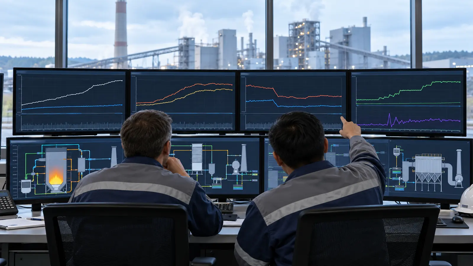
A safer control hierarchy: physical limits first, optimization second
1. Establish the minimum permitted operating envelope
Document the catalyst vendor’s minimum and maximum temperatures, allowable excursion duration, ammonia-injection permissives, NH3-slip requirement, NOx permit basis and ramp-rate assumptions. Confirm instrument locations: the temperature relevant to the catalyst is not necessarily the same as the boiler’s general flue-gas temperature indication.
If the SCR inlet is below the approved limit, follow the plant’s approved low-temperature and emissions procedure. Do not treat AI optimization or a higher reagent rate as permission to bypass a temperature interlock.
2. Fix measurement quality and delay
Time-align boiler load, SCR inlet temperature, inlet/outlet NOx, O2, NH3 flow, slip, AIG valve positions and air-preheater ΔP. Confirm CEMS sample-line and analyzer delay by test rather than assuming a fixed number of minutes. Where multipoint or in-situ measurement is considered, establish calibration, maintenance access and representative coverage. Faster measurements help only when they are reliable and integrated into a stable control strategy.
3. Combine feed-forward with measured feedback
Load, inlet NOx and inlet temperature can provide a feed-forward estimate of ammonia demand; outlet NOx feedback can trim it. This is established SCR control practice described in the US EPA SCR Cost Manual. Predictive or AI models may improve that estimate, but they should have constraint handling, confidence checks, operator override and a safe fallback mode. Validate performance separately at stable low load, downward ramps and upward ramps.
4. Tune distribution, not just total ammonia
An average NH3/NOx ratio can look acceptable while individual AIG zones are wrong. Compare cross-sectional NOx, velocity and temperature measurements at the relevant load bands. Check nozzles, mixing devices, dampers and catalyst-face ash accumulation. CFD can support a hypothesis, but field measurements are needed to confirm the retrofit or tuning result.
5. Consider hardware only against a defined constraint
If temperature is the binding limit, an economizer gas-side or water-side bypass, heating measure, or catalyst change may be assessed. Each option has efficiency, thermal-stress, safety and cost consequences. DOE/NETL specifically cautions that a change to economizer temperature control must consider feedwater temperature and economizer steaming risk. DOE/NETL flexibility assessment If distribution is the limit, AIG and duct-flow modifications may matter more than a new catalyst layer. If catalyst activity is the limit, use a qualified activity test and the lifecycle process described in our SCR catalyst lifecycle guide.
A commissioning checklist for a low-load SCR improvement project
| Work package | Minimum evidence to collect | Acceptance question |
|---|---|---|
| Operating envelope | Catalyst specification, boiler load range, temperature and excursion history | Is ammonia injection permitted at every intended load? |
| Baseline emissions | Time-aligned NOx, O2, NH3 flow/slip and permit basis | What margin exists at steady load and during ramps? |
| Flow and AIG distribution | Traverse data by load band, zone settings, nozzle condition | Are local overfeed and underfeed visible and correctable? |
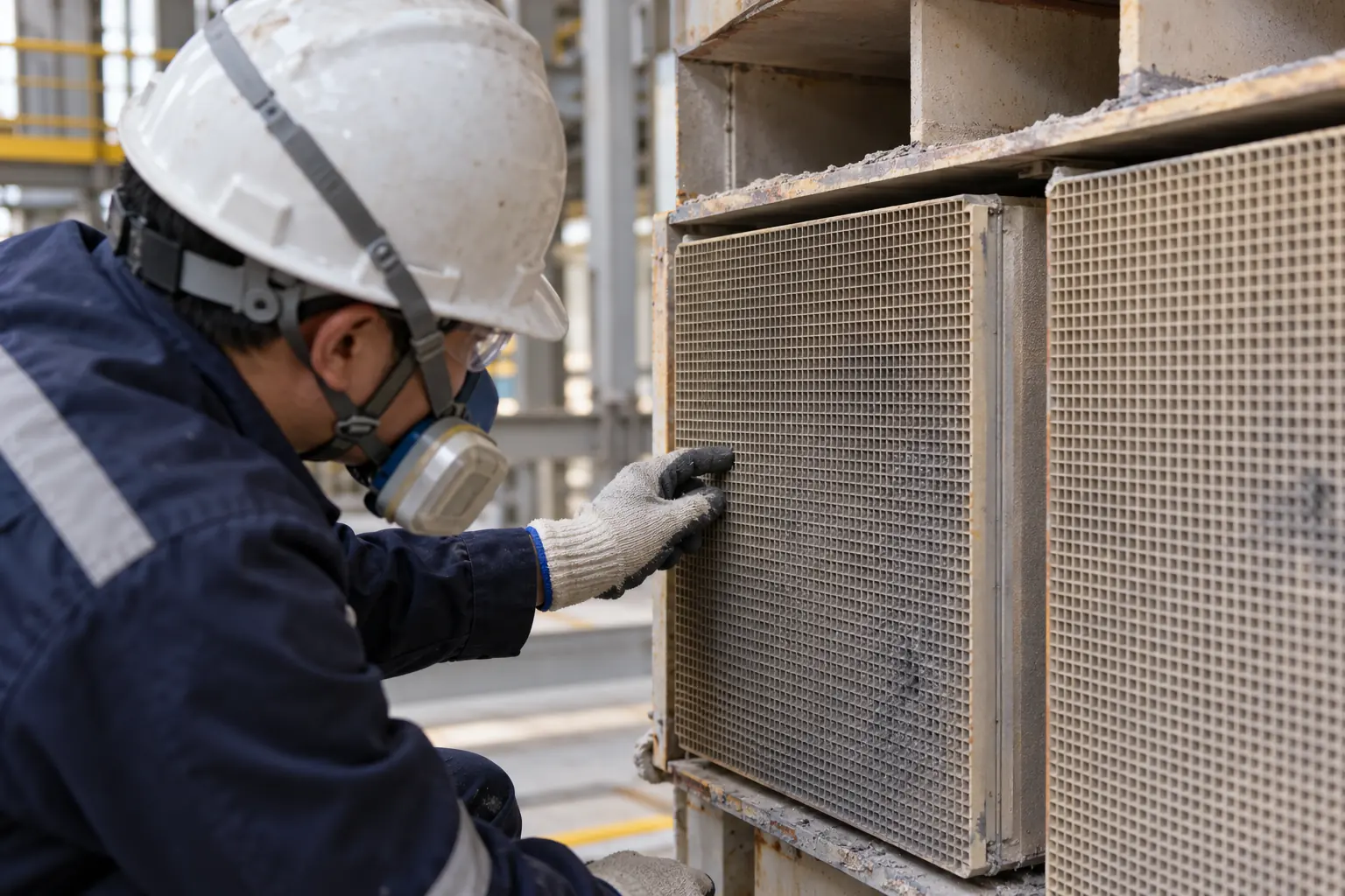
| Fouling and catalyst health | Layer ΔP, air-heater ΔP, inspection photos, activity results | Is performance limited by deposits, deactivation or controls? |
| Control validation | Analyzer delay, model test results, fallback logic, operator sign-off | Does the new strategy remain stable during disturbances and sensor faults? |
| Post-change review | Before/after data at comparable fuel and load conditions | Did NOx compliance improve without worsening slip, ΔP or reagent use? |
Define success using a test protocol, not a single best-looking trend. The protocol should specify load bands, ramp rates, fuel conditions, averaging periods, measurement uncertainty and which plant controls remain in service.
Yuanchen’s AI Environmental Island: where it may fit
Yuanchen’s original company article describes an AI Environmental Island approach spanning denitrification, desulfurization and dust collection. It proposes faster in-situ NOx sensing, a model that anticipates load changes, and coordinated feed-forward/feedback control. These are potentially useful tools for dynamic operation, especially when legacy sampling delay and static AIG settings are verified constraints. They are not substitutes for maintaining catalyst temperature or meeting the plant’s safety and emissions rules.
The source article describes a Xinjiang coal unit with an operating range of 130–650 MW and reports continuous AI-assisted control across that range. This is a company-reported project description, not an independently audited performance study. The source does not include the unit’s design capacity, baseline and post-project NOx/NH3 data, averaging periods, number of test days, fuel variation, override frequency or third-party acceptance report. Therefore, this guide does not claim a quantified NOx, reagent or energy saving—or that operators were never required to intervene. A procurement team should request those records before treating the project as evidence for its own unit.
The company article also cites an “international advanced” technical appraisal. Because the certificate number, scope and appraisal report were not supplied with the article, we have not used that phrase as a performance claim here.
Questions plant teams frequently ask
Can I keep injecting ammonia below the normal SCR temperature window?
Only if the plant’s catalyst specification and approved operating procedure explicitly allow it. Below-limit operation can lose conversion margin and increase deposit risk. The correct response is a site-specific operating decision, not a universal temperature cutoff.
Will a low-temperature catalyst solve deep-turndown problems by itself?
Not necessarily. It may expand the temperature envelope, but inlet distribution, ash, SO3, ammonia-slip limits, pressure drop and control delay still need to be engineered. Request performance guarantees for the actual gas composition and load profile.
What is the quickest useful data package to send a supplier?
Send 15-minute or higher-resolution time-aligned trends across representative low-load events: unit load, fuel, SCR inlet temperature, inlet/outlet NOx and O2, NH3 flow and measured slip, AIG zone commands, catalyst-layer and air-preheater ΔP, plus reactor drawings and the catalyst datasheet. State sensor locations and CEMS delay. Unknown values should be marked unknown, not estimated silently.
Bottom line
Low-load SCR reliability is an operating-system question. Start with the catalyst’s permitted temperature and verified measurements; then diagnose distribution and fouling, improve feed-forward/feedback control, and only then choose a hardware or catalyst retrofit. For a site-specific review, share the data package above with Yuanchen’s SCR catalyst team and ask for a proposal that states its assumptions, test method and acceptance criteria.